# PCF8575_library
**Repository Path**: liuzewen/PCF8575_library
## Basic Information
- **Project Name**: PCF8575_library
- **Description**: IO拓展芯片PCF8575的Arduino库
- **Primary Language**: C++
- **License**: MIT
- **Default Branch**: master
- **Homepage**: None
- **GVP Project**: No
## Statistics
- **Stars**: 0
- **Forks**: 0
- **Created**: 2022-01-20
- **Last Updated**: 2024-05-30
## Categories & Tags
**Categories**: Uncategorized
**Tags**: None
## README


###Additional information and document update here on my site: [pcf8575 Article](https://www.mischianti.org/2019/07/22/pcf8575-i2c-16-bit-digital-i-o-expander/).
###If you need less pins [here](https://www.mischianti.org/2019/01/02/pcf8574-i2c-digital-i-o-expander-fast-easy-usage/) you can find pcf8574 discrete 8bit version of the IC.
Library to use i2c analog IC with arduino and esp8266. Can read and write digital value with only 2 wire (perfect for ESP-01).
Tutorial:
To download. click the DOWNLOADS button in the top right corner, rename the uncompressed folder PCF8575. Check that the PCF8575 folder contains `PCF8575\\.cpp` and `PCF8575.h`. Place the DHT library folder your `/libraries/` folder. You may need to create the libraries subfolder if its your first library. Restart the IDE.
# Reef complete PCF8575 PCF8575AP digital input and output expander with i2c bus.
I try to simplify the use of this IC, with a minimal set of operation.
PCF8575 address map 0x20 default
Constructor:
you must pas the address of i2c (to check the adress use this guide [I2cScanner](https://playground.arduino.cc/Main/I2cScanner))
```cpp
PCF8575(uint8_t address);
```
for esp8266 if you want specify SDA e SCL pin use this:
```cpp
PCF8575(uint8_t address, uint8_t sda, uint8_t scl);
```
You must set input/output mode:
```cpp
pcf8575.pinMode(P0, OUTPUT);
pcf8575.pinMode(P1, INPUT);
pcf8575.pinMode(P2, INPUT);
```
then IC as you can see in the image have 8 digital input/output:

So to read all analog input in one trasmission you can do (even if I use a 10millis debounce time to prevent too much read from i2c):
```cpp
PCF8575::DigitalInput di = PCF8575.digitalReadAll();
Serial.print(di.p0);
Serial.print(" - ");
Serial.print(di.p1);
Serial.print(" - ");
Serial.print(di.p2);
Serial.print(" - ");
Serial.println(di.p3);
```
To follow a request (you can see It on [issue #5](https://github.com/xreef/PCF8575_library/issues/5)) I create a define variable to work with low memori device, if you decomment this line on .h file of the library:
```cpp
// #define PCF8575_LOW_MEMORY
```
Enable low memory props and gain about 7byte of memory, and you must use the method to read all like so:
```cpp
byte di = pcf8575.digitalReadAll();
Serial.print("READ VALUE FROM PCF: ");
Serial.println(di, BIN);
```
where di is a byte like 11100011110001, so you must do a bitwise operation to get the data, operation that I already do in the "normal" mode, here an example:
```cpp
p0 = ((di & bit(0))>0)?HIGH:LOW;
p1 = ((di & bit(1))>0)?HIGH:LOW;
p2 = ((di & bit(2))>0)?HIGH:LOW;
p3 = ((di & bit(3))>0)?HIGH:LOW;
p4 = ((di & bit(4))>0)?HIGH:LOW;
p5 = ((di & bit(5))>0)?HIGH:LOW;
p6 = ((di & bit(6))>0)?HIGH:LOW;
p7 = ((di & bit(7))>0)?HIGH:LOW;
```
if you want read a single input:
```cpp
int p1Digital = PCF8575.digitalRead(P1); // read P1
```
If you want write a digital value you must do:
```cpp
PCF8575.digitalWrite(P1, HIGH);
```
or:
```cpp
PCF8575.digitalWrite(P1, LOW);
```
You can also use interrupt pin:
You must initialize the pin and the function to call when interrupt raised from PCF8575
```cpp
// Function interrupt
void keyPressedOnPCF8575();
// Set i2c address
PCF8575 pcf8575(0x39, ARDUINO_UNO_INTERRUPT_PIN, keyPressedOnPCF8575);
```
Remember you can't use Serial or Wire on interrupt function.
The better way is to set only a variable to read on loop:
```cpp
void keyPressedOnPCF8575(){
// Interrupt called (No Serial no read no wire in this function, and DEBUG disabled on PCF library)
keyPressed = true;
}
```
For the examples I use this wire schema on breadboard:

[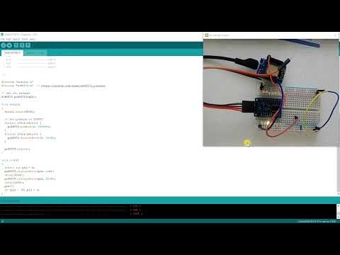](https://youtu.be/jWeHzBLeN6s "Test pcf8575")