| Type | Name | Default | Description |
|---|---|---|---|
| OSPTransferFunction | transferFunction | transfer function to use | |
| vec2f | voxelRange | minimum and maximum of the scalar values | |
| bool | gradientShadingEnabled | false | volume is rendered with surface shading wrt. to normalized gradient |
| bool | preIntegration | false | use pre-integration for transfer function lookups |
| bool | singleShade | true | shade only at the point of maximum intensity |
| bool | adaptiveSampling | true | adapt ray step size based on opacity |
| float | adaptiveScalar | 15 | modifier for adaptive step size |
| float | adaptiveMaxSamplingRate | 2 | maximum sampling rate for adaptive sampling |
| float | samplingRate | 0.125 | sampling rate of the volume (this is the minimum step size for adaptive sampling) |
| vec3f | specular | gray 0.3 | specular color for shading |
| vec3f | volumeClippingBoxLower | disabled | lower coordinate (in object-space) to clip the volume values |
| vec3f | volumeClippingBoxUpper | disabled | upper coordinate (in object-space) to clip the volume values |
| Type | Name | Default | Description |
|---|---|---|---|
| vec3i | dimensions | number of voxels in each dimension (x, y, z) | |
| string | voxelType | data type of each voxel, currently supported are: | |
| “uchar” (8 bit unsigned integer) | |||
| “short” (16 bit signed integer) | |||
| “ushort” (16 bit unsigned integer) | |||
| “float” (32 bit single precision floating point) | |||
| “double” (64 bit double precision floating point) | |||
| vec3f | gridOrigin | (0, 0, 0) | origin of the grid in world-space |
| vec3f | gridSpacing | (1, 1, 1) | size of the grid cells in world-space |
| Type | Name | Default | Description |
|---|---|---|---|
| vec3f | gridOrigin | (0, 0, 0) | origin of the grid in world-space |
| vec3f | gridSpacing | (1, 1, 1) | size of the grid cells in world-space |
| string | amrMethod | current | sampling method; valid values are “finest”, “current”, or “octant” |
| string | voxelType | undefined | data type of each voxel, currently supported are: |
| “uchar” (8 bit unsigned integer) | |||
| “short” (16 bit signed integer) | |||
| “ushort” (16 bit unsigned integer) | |||
| “float” (32 bit single precision floating point) | |||
| “double” (64 bit double precision floating point) | |||
| OSPData | brickInfo | array of info defining each brick | |
| OSPData | brickData | array of handles to per-brick voxel data |
| Type | Name | Default | Description |
|---|---|---|---|
| vec3f[] | vertices | data array of vertex positions | |
| float[] | field | data array of vertex data values to be sampled | |
| float[] | cellField | data array of cell data values to be sampled | |
| vec4i[] | indices | data array of tetrahedra indices (into vertices and field) | |
| string | hexMethod | planar | “planar” (faster, assumes planar sides) or “nonplanar” |
| bool | precomputedNormals | true | whether to accelerate by precomputing, at a cost of 72 bytes/cell |
| Type | Name | Default | Description |
|---|---|---|---|
| float | radius | 0.01 | radius of all spheres (if offset_radius is not used) |
| OSPData | spheres | NULL | memory holding the spatial data of all spheres |
| int | bytes_per_sphere | 16 | size (in bytes) of each sphere within the spheres array |
| int | offset_center | 0 | offset (in bytes) of each sphere’s “vec3f center” position (in object-space) within the spheres array |
| int | offset_radius | -1 | offset (in bytes) of each sphere’s “float radius” within the spheres array (-1 means disabled and use radius) |
| int | offset_colorID | -1 | offset (in bytes) of each sphere’s “int colorID” within the spheres array (-1 means disabled and use the shared material color) |
| vec4f[] / vec3f(a)[] / vec4uc | color | NULL | data array of colors (RGBA/RGB), color is constant for each sphere |
| int | color_offset | 0 | offset (in bytes) to the start of the color data in color |
| int | color_format | color.data_type |
the format of the color data. Can be one of: OSP_FLOAT4, OSP_FLOAT3, OSP_FLOAT3A or OSP_UCHAR4. Defaults to the type of data in color |
| int | color_stride | sizeof(color_format) |
stride (in bytes) between each color element in the color array. Defaults to the size of a single element of type color_format |
| vec2f[] | texcoord | NULL | data array of texture coordinates, coordinate is constant for each sphere |
| Type | Name | Default | Description |
|---|---|---|---|
| float | radius | 0.01 | radius of all cylinders (if offset_radius is not used) |
| OSPData | cylinders | NULL | memory holding the spatial data of all cylinders |
| int | bytes_per_cylinder | 24 | size (in bytes) of each cylinder within the cylinders array |
| int | offset_v0 | 0 | offset (in bytes) of each cylinder’s “vec3f v0” position (the start vertex, in object-space) within the cylinders array |
| int | offset_v1 | 12 | offset (in bytes) of each cylinder’s “vec3f v1” position (the end vertex, in object-space) within the cylinders array |
| int | offset_radius | -1 | offset (in bytes) of each cylinder’s “float radius” within the cylinders array (-1 means disabled and use radius instead) |
| vec4f[] / vec3f(a)[] | color | NULL | data array of colors (RGBA/RGB), color is constant for each cylinder |
| OSPData | texcoord | NULL | data array of texture coordinates, in pairs (each a vec2f at vertex v0 and v1) |
| Type | Name | Description |
|---|---|---|
| float | radius | global radius of all streamlines (if per-vertex radius is not used), default 0.01 |
| bool | smooth | enable curve interpolation, default off (always on if per-vertex radius is used) |
| vec3fa[] / vec4f[] | vertex | data array of all vertex position (and optional radius) for all streamlines |
| vec4f[] | vertex.color | data array of corresponding vertex colors (RGBA) |
| float[] | vertex.radius | data array of corresponding vertex radius |
| int32[] | index | data array of indices to the first vertex of a link |
| Type | Name | Description |
|---|---|---|
| string | curveType | “flat” (ray oriented), “round” (circular cross section), “ribbon” (normal oriented flat curve) |
| string | curveBasis | “linear”, “bezier”, “bspline”, “hermite” |
| vec4f[] | vertex | data array of vertex position and radius |
| int32[] | index | data array of indices to the first vertex or tangent of a curve segment |
| vec3f[] | vertex.normal | data array of curve normals (only for “ribbon” curves) |
| vec3f[] | vertex.tangent | data array of curve tangents (only for “hermite” curves) |
| Type | Name | Default | Description |
|---|---|---|---|
| OSPModel | model | the model to render | |
| OSPCamera | camera | the camera to be used for rendering | |
| OSPLight[] | lights | data array with handles of the lights | |
| int | spp | 1 | samples per pixel |
| int | maxDepth | 20 | maximum ray recursion depth |
| float | minContribution | 0.001 | sample contributions below this value will be neglected to speedup rendering |
| float | varianceThreshold | 0 | threshold for adaptive accumulation |
| Type | Name | Default | Description |
|---|---|---|---|
| bool | shadowsEnabled | false | whether to compute (hard) shadows |
| int | aoSamples | 0 | number of rays per sample to compute ambient occlusion |
| float | aoDistance | 1020 | maximum distance to consider for ambient occlusion |
| bool | aoTransparencyEnabled | false | whether object transparency is respected when computing ambient occlusion (slower) |
| bool | oneSidedLighting | true | if true, backfacing surfaces (wrt. light source) receive no illumination |
| float / vec3f / vec4f | bgColor | black, transparent | background color and alpha (RGBA) |
| OSPTexture | maxDepthTexture | NULL | screen-sized float texture with maximum far distance per pixel (use texture type ‘texture2d’) |
| Type | Name | Default | Description |
|---|---|---|---|
| int | rouletteDepth | 5 | ray recursion depth at which to start Russian roulette termination |
| float | maxContribution | ∞ | samples are clamped to this value before they are accumulated into the framebuffer |
| OSPTexture | backplate | NULL | texture image used as background, replacing visible lights in infinity (e.g., the HDRI light) |
| Type | Name | Default | Description |
|---|---|---|---|
| bool | dynamicScene | false | use RTC_SCENE_DYNAMIC flag (faster BVH build, slower ray traversal), otherwise uses RTC_SCENE_STATIC flag (faster ray traversal, slightly slower BVH build) |
| bool | compactMode | false | tell Embree to use a more compact BVH in memory by trading ray traversal performance |
| bool | robustMode | false | tell Embree to enable more robust ray intersection code paths (slightly slower) |
| Type | Name | Description |
|---|---|---|
| vec3f(a) | position | the center of the spotlight, in world-space |
| vec3f(a) | direction | main emission direction of the spot |
| float | openingAngle | full opening angle (in degree) of the spot; outside of this cone is no illumination |
| float | penumbraAngle | size (angle in degree) of the “penumbra”, the region between the rim (of the illumination cone) and full intensity of the spot; should be smaller than half of openingAngle |
| float | radius | the size of the spotlight, the radius of a disk with normal direction |
| Type | Name | Description |
|---|---|---|
| vec3f(a) | up | up direction of the light in world-space |
| vec3f(a) | dir | direction to which the center of the texture will be mapped to (analog to panoramic camera) |
| OSPTexture | map | environment map in latitude / longitude format |
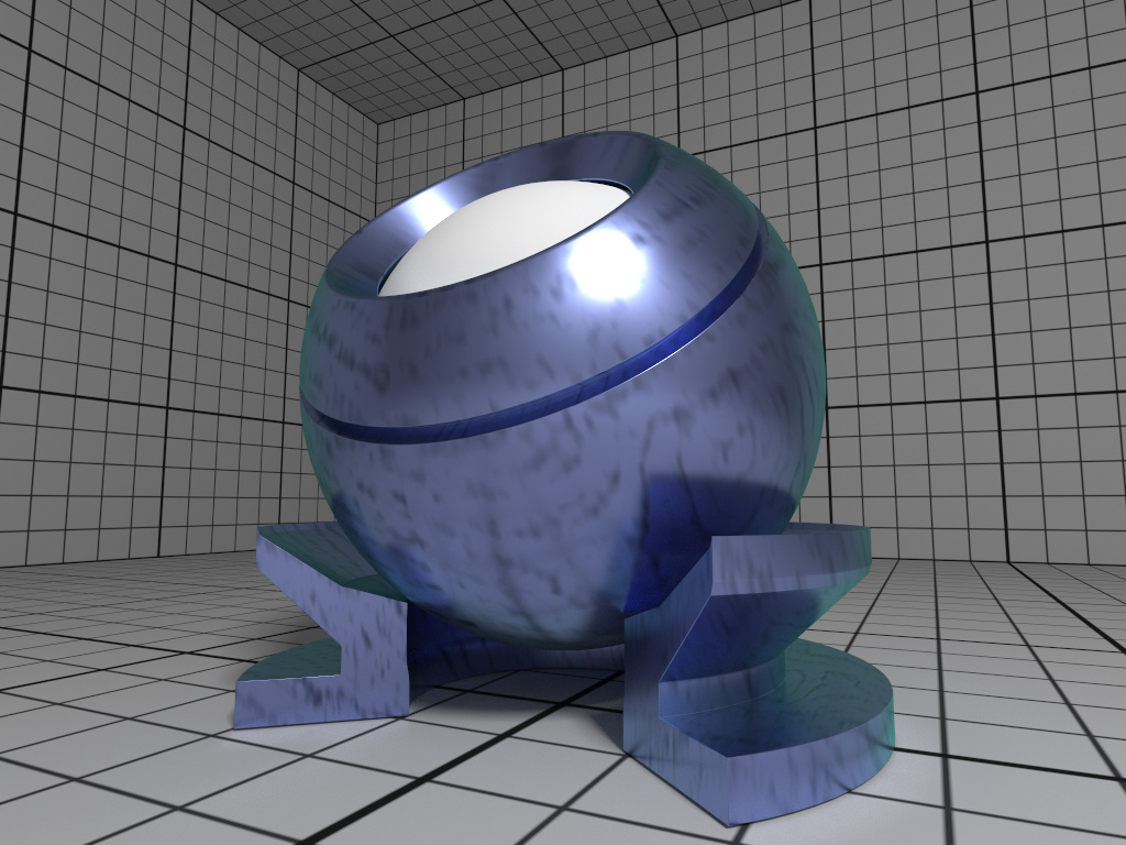
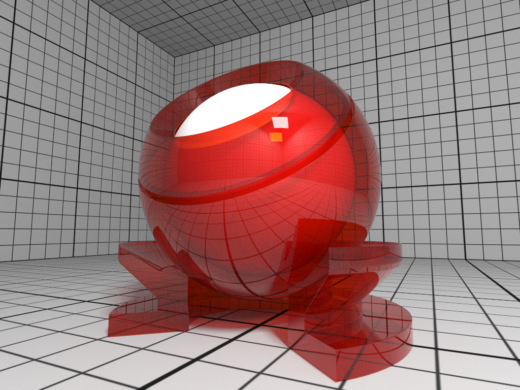
| Type | Name | Default | Description |
|---|---|---|---|
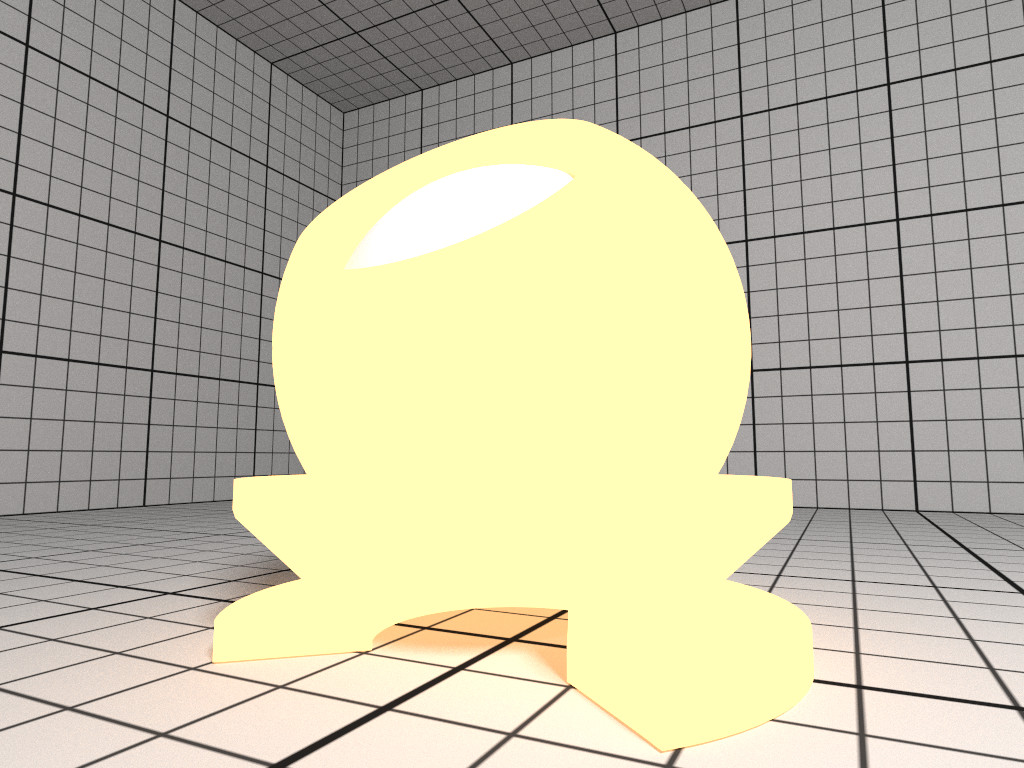
| vec3f | baseColor | white 0.8 | base reflectivity (diffuse and/or metallic) |
| vec3f | edgeColor | white | edge tint (metallic only) |
| float | metallic | 0 | mix between dielectric (diffuse and/or specular) and metallic (specular only with complex IOR) in [0–1] |
| float | diffuse | 1 | diffuse reflection weight in [0–1] |
| float | specular | 1 | specular reflection/transmission weight in [0–1] |
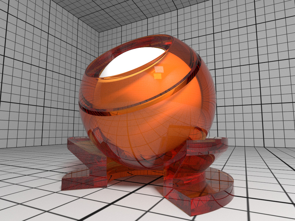
| float | ior | 1 | dielectric index of refraction |
| float | transmission | 0 | specular transmission weight in [0–1] |
| vec3f | transmissionColor | white | attenuated color due to transmission (Beer’s law) |
| float | transmissionDepth | 1 | distance at which color attenuation is equal to transmissionColor |
| float | roughness | 0 | diffuse and specular roughness in [0–1], 0 is perfectly smooth |
| float | anisotropy | 0 | amount of specular anisotropy in [0–1] |
| float | rotation | 0 | rotation of the direction of anisotropy in [0–1], 1 is going full circle |
| float | normal | 1 | default normal map/scale for all layers |
| float | baseNormal | 1 | base normal map/scale (overrides default normal) |
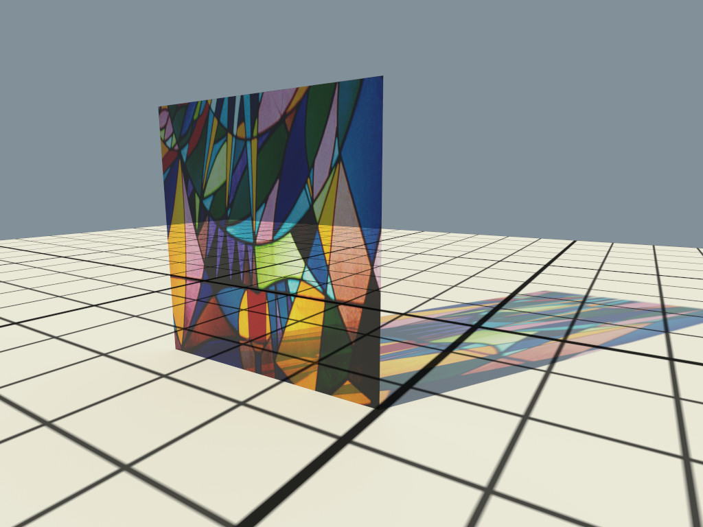
| bool | thin | false | flag specifying whether the material is thin or solid |
| float | thickness | 1 | thickness of the material (thin only), affects the amount of color attenuation due to specular transmission |
| float | backlight | 0 | amount of diffuse transmission (thin only) in [0–2], 1 is 50% reflection and 50% transmission, 2 is transmission only |
| float | coat | 0 | clear coat layer weight in [0–1] |
| float | coatIor | 1.5 | clear coat index of refraction |
| vec3f | coatColor | white | clear coat color tint |
| float | coatThickness | 1 | clear coat thickness, affects the amount of color attenuation |
| float | coatRoughness | 0 | clear coat roughness in [0–1], 0 is perfectly smooth |
| float | coatNormal | 1 | clear coat normal map/scale (overrides default normal) |
| float | sheen | 0 | sheen layer weight in [0–1] |
| vec3f | sheenColor | white | sheen color tint |
| float | sheenTint | 0 | how much sheen is tinted from sheenColor toward baseColor |
| float | sheenRoughness | 0.2 | sheen roughness in [0–1], 0 is perfectly smooth |
| float | opacity | 1 | cut-out opacity/transparency, 1 is fully opaque |
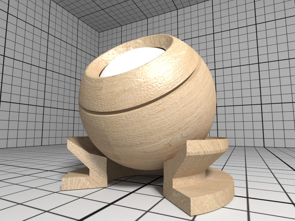
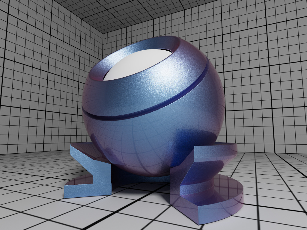
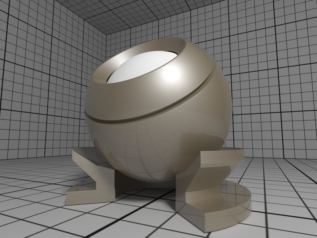
| Type | Name | Default | Description |
|---|---|---|---|
| vec3f | baseColor | white 0.8 | diffuse base reflectivity |
| float | roughness | 0 | diffuse roughness in [0–1], 0 is perfectly smooth |
| float | normal | 1 | normal map/scale |
| float | flakeDensity | 0 | density of metallic flakes in [0–1], 0 disables flakes, 1 fully covers the surface with flakes |
| float | flakeScale | 100 | scale of the flake structure, higher values increase the amount of flakes |
| float | flakeSpread | 0.3 | flake spread in [0–1] |
| float | flakeJitter | 0.75 | flake randomness in [0–1] |
| float | flakeRoughness | 0.3 | flake roughness in [0–1], 0 is perfectly smooth |
| float | coat | 1 | clear coat layer weight in [0–1] |
| float | coatIor | 1.5 | clear coat index of refraction |
| vec3f | coatColor | white | clear coat color tint |
| float | coatThickness | 1 | clear coat thickness, affects the amount of color attenuation |
| float | coatRoughness | 0 | clear coat roughness in [0–1], 0 is perfectly smooth |
| float | coatNormal | 1 | clear coat normal map/scale |
| vec3f | flipflopColor | white | reflectivity of coated flakes at grazing angle, used together with coatColor produces a pearlescent paint |
| float | flipflopFalloff | 1 | flip flop color falloff, 1 disables the flip flop effect |
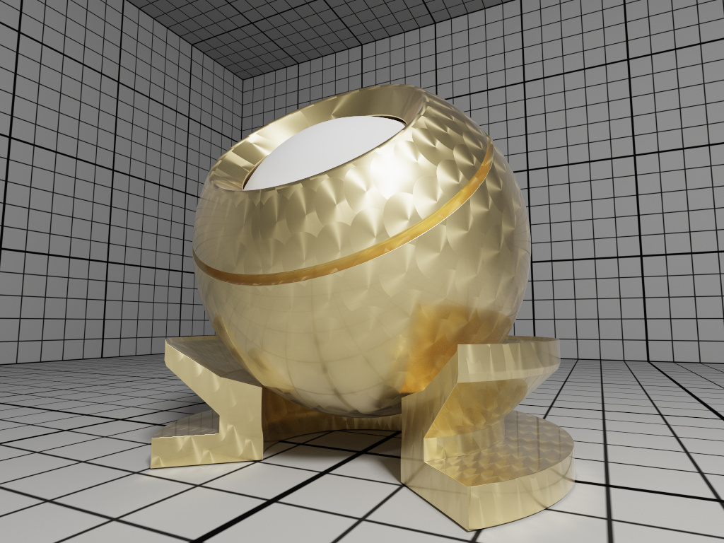
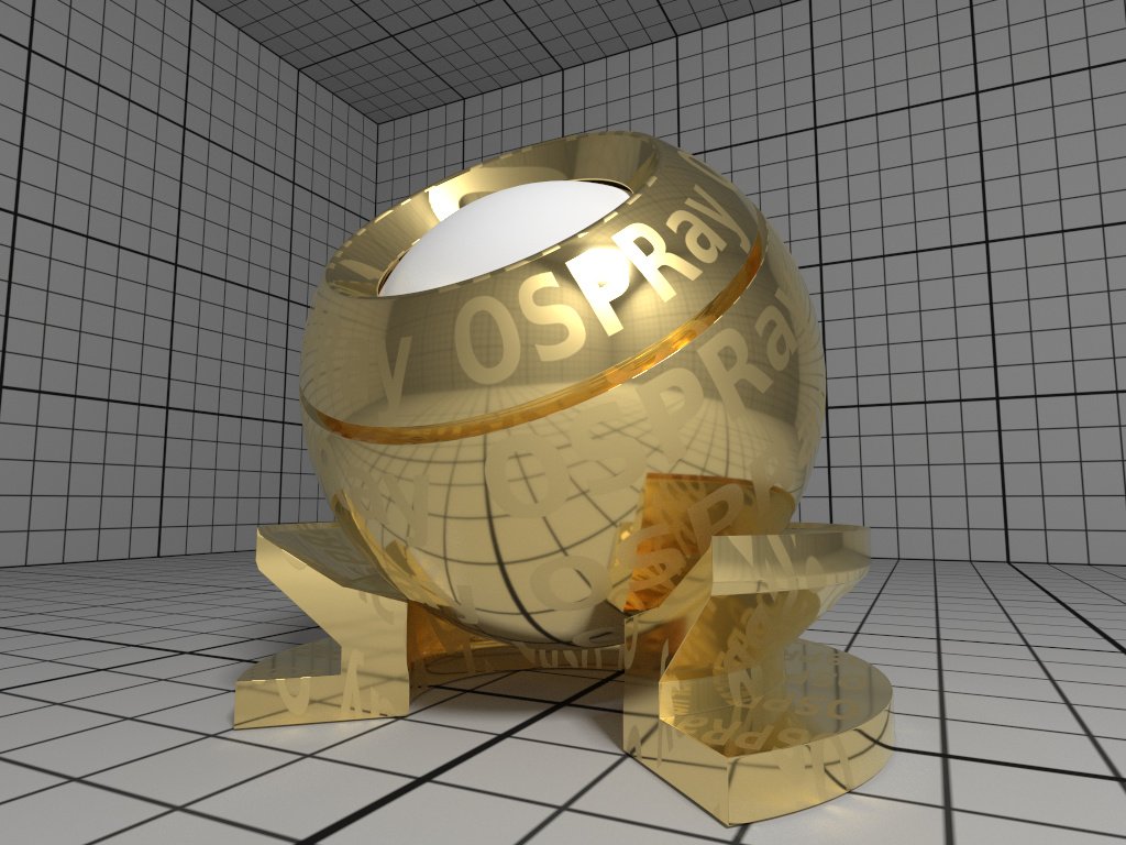
| Type | Name | Default | Description |
|---|---|---|---|
| vec3f[] | ior | Aluminium | data array of spectral samples of complex refractive index, each entry in the form (wavelength, eta, k), ordered by wavelength (which is in nm) |
| vec3f | eta | RGB complex refractive index, real part | |
| vec3f | k | RGB complex refractive index, imaginary part | |
| float | roughness | 0.1 | roughness in [0–1], 0 is perfect mirror |
| Type | Name | Description |
|---|---|---|
| float | fovy | the field of view (angle in degree) of the frame’s height |
| float | aspect | ratio of width by height of the frame (and image region) |
| float | apertureRadius | size of the aperture, controls the depth of field |
| float | focusDistance | distance at where the image is sharpest when depth of field is enabled |
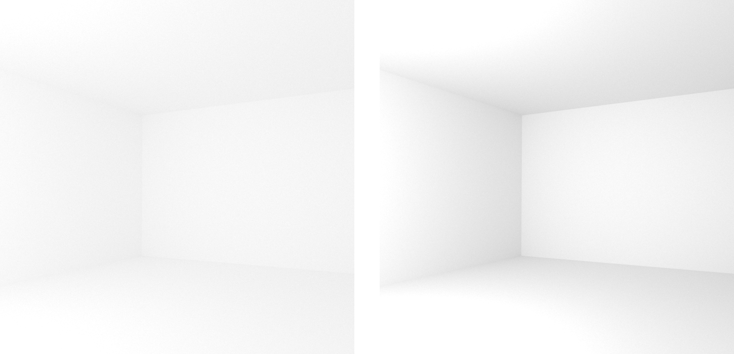
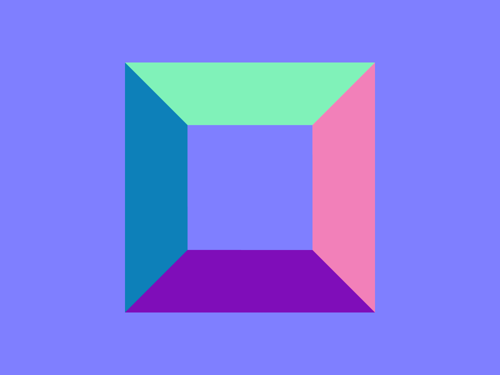
| bool | architectural | vertical edges are projected to be parallel |
| int | stereoMode | 0: no stereo (default), 1: left eye, 2: right eye, 3: side-by-side |
| float | interpupillaryDistance | distance between left and right eye when stereo is enabled |
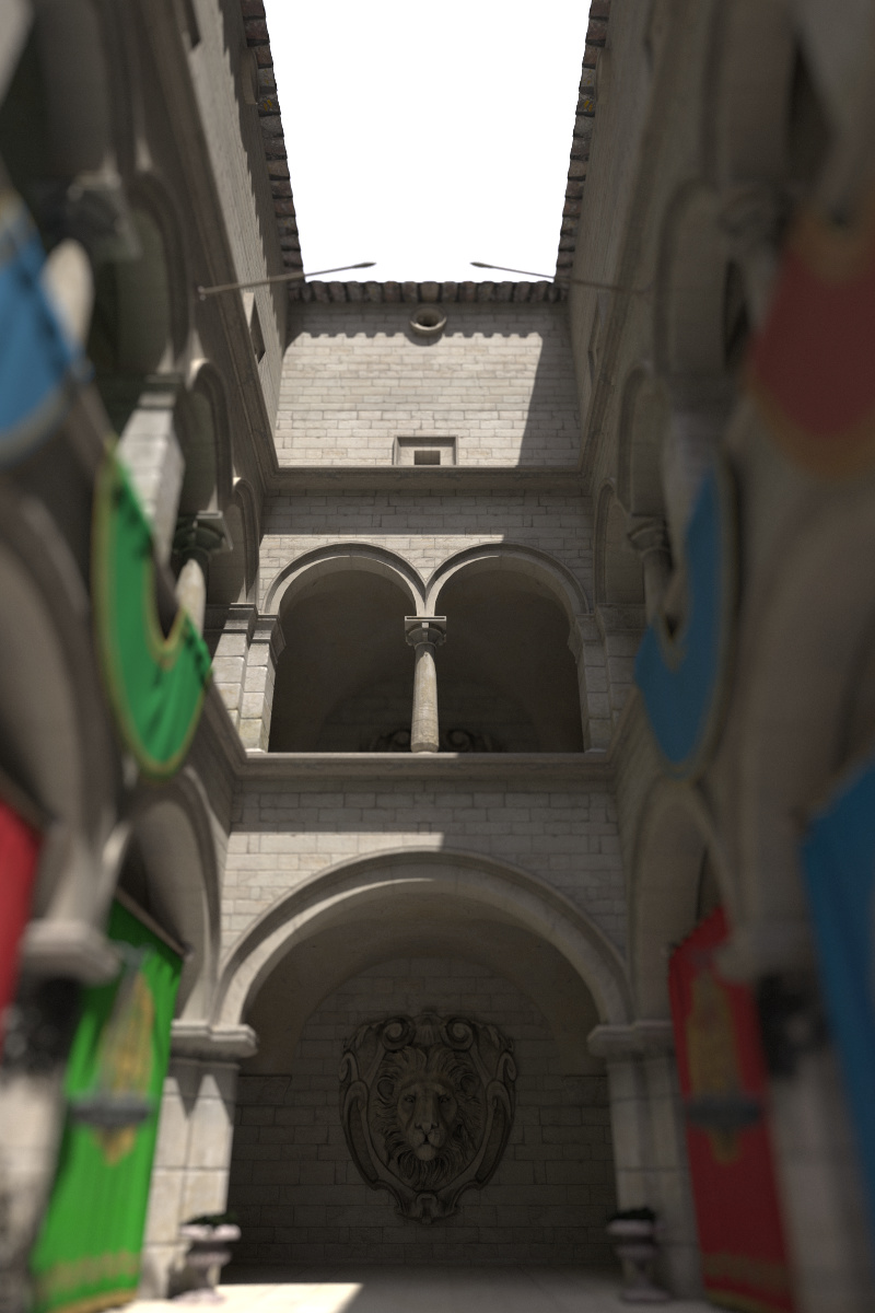
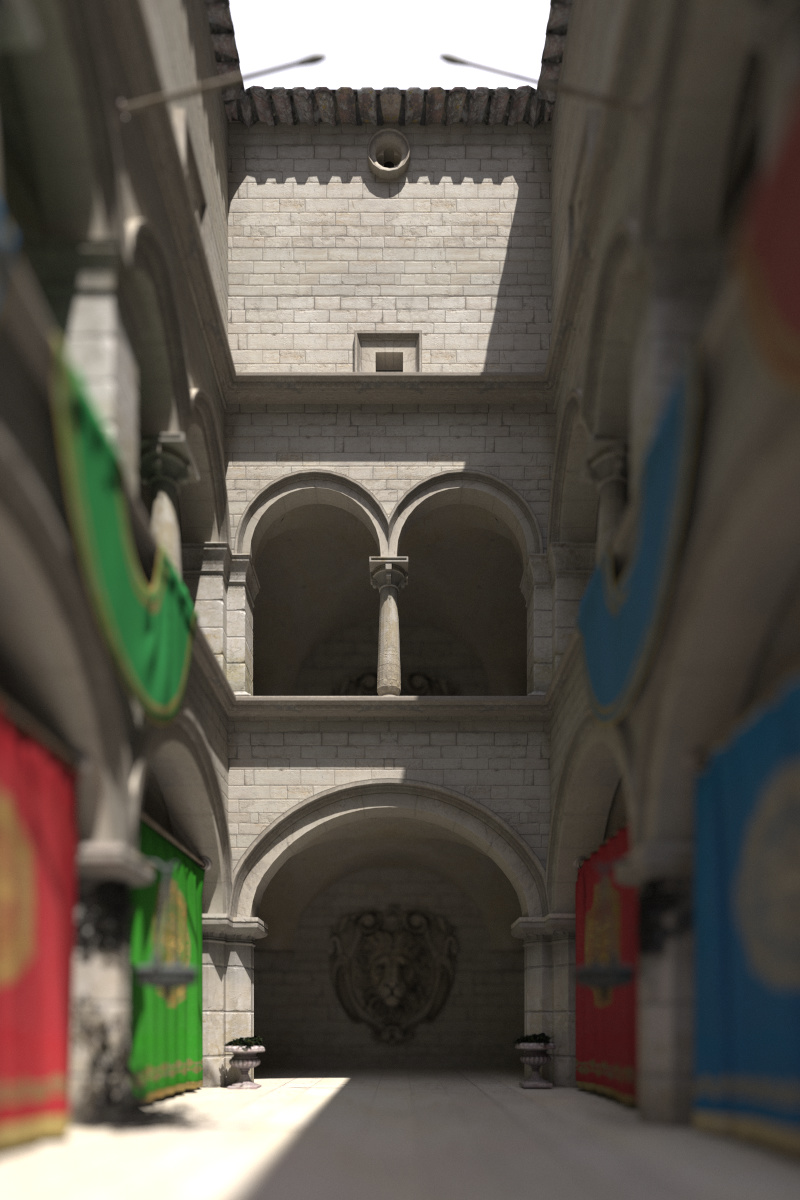
architectural flag corrects the perspective projection distortion, resulting in parallel vertical edges.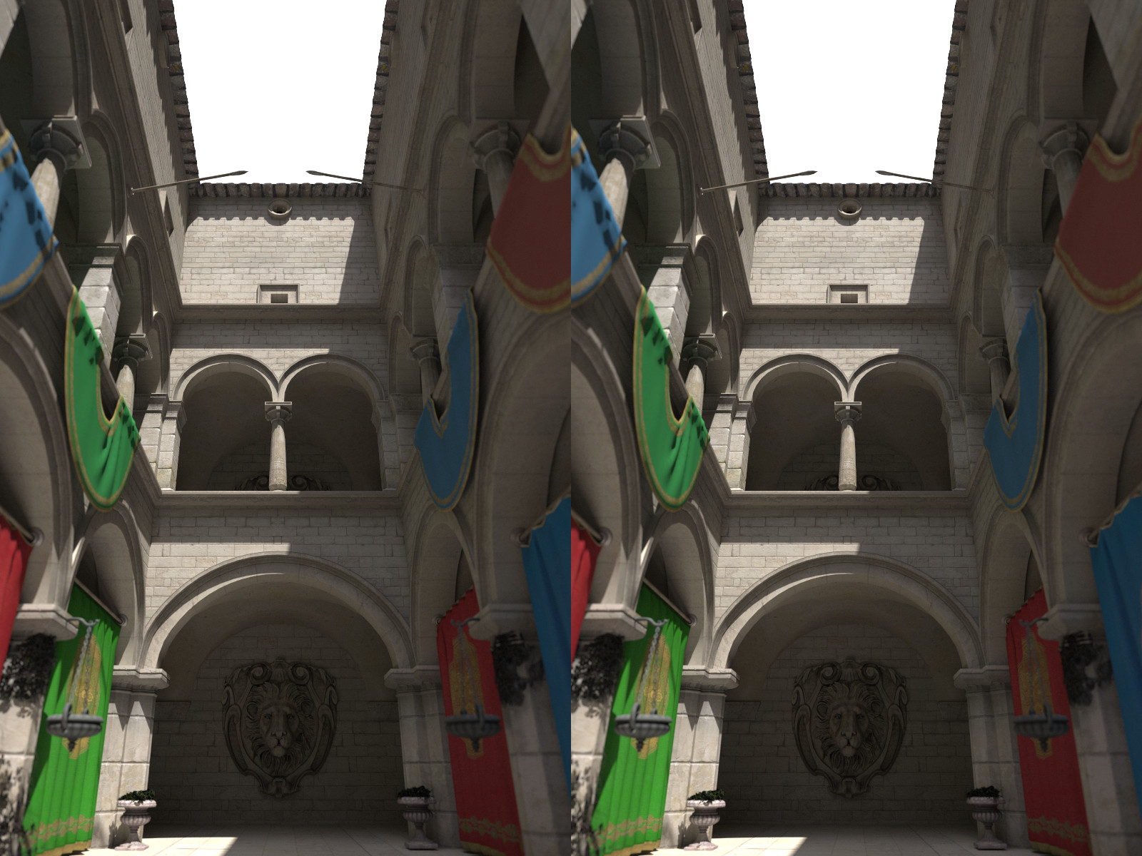
stereoMode side-by-side.
| Type | Name | Default | Description |
|---|---|---|---|
| float | contrast | 1.6773 | contrast (toe of the curve); typically is in [1–2] |
| float | shoulder | 0.9714 | highlight compression (shoulder of the curve); typically is in [0.9–1] |
| float | midIn | 0.18 | mid-level anchor input; default is 18% gray |
| float | midOut | 0.18 | mid-level anchor output; default is 18% gray |
| float | hdrMax | 11.0785 | maximum HDR input that is not clipped |
| bool | acesColor | true | apply the ACES color transforms |
| Type | Name | Description |
|---|---|---|
| void* | worldCommunicator | A pointer to the MPI_Comm which should be used as OSPRay’s world communicator. This will set how many ranks OSPRay should expect to participate in rendering. The default is MPI_COMM_WORLD where all ranks are expected to participate in rendering. |
| Type | Name | Description |
|---|---|---|
| int | id | An integer that uniquely identifies this piece of distributed data. For example, in a common case of one sub-brick per-rank, this would just be the region’s MPI rank. Multiple ranks can specify models with the same ID, in which case the rendering work for the model will be shared among them. |
| vec3f | region.lower | Override the original model geometry + volume bounds with a custom lower bound position. This can be used to clip geometry in the case the objects cross over to another region owned by a different node. For example, rendering a set of spheres with radius. |
| vec3f | region.upper | Override the original model geometry + volume bounds with a custom upper bound position. |
| Type | Name | Default | Description |
|---|---|---|---|
| OSPModel/OSPModel[] | model | NULL | the model to render, can optionally be a data array of multiple models |
| OSPModel/OSPModel[] | ghostModel | NULL | the optional model containing the ghost geometry for ambient occlusion; when setting a data array for both model and ghostModel, each individual ghost model shadows only its corresponding model |
| OSPLight[] | lights | data array with handles of the lights | |
| int | aoSamples | 0 | number of rays per sample to compute ambient occlusion |
| bool | aoTransparencyEnabled | false | whether object transparency is respected when computing ambient occlusion (slower) |
| bool | oneSidedLighting | true | if true, backfacing surfaces (wrt. light source) receive no illumination |