


 | Ball bearing
  | Aluminum tube
  |M3 screws | M4 screws & nuts
 | iPower Motor GM4108H-120T | [iFlight webshop](https://shop.iflight-rc.com/index.php?route=product/product&product_id=217&search=GM4108H-120T) | 35$
 | BGM 4108 120T | [Ebay](https://www.ebay.com/itm/gimbal-brushless-motor-BGM-4108-120T-hollow-silver-version/261539739163?hash=item3ce4fbb61b:g:4iAAAOSwPe1Tzdhy) | 30$
 | BGM4108-150HS | [Ebay](https://www.ebay.com/itm/New-Brushless-Gimbal-Motor-BGM4108-150HS-24N22P-for-Sony-NEX5-7-Camera-Mount-DIY/261903969970?epid=1539061157&hash=item3cfab16eb2:g:0EIAAOSwiLdWBLrX) | 32$
### Position sensors
In this project I am using two encoders to track the movement of the pendulum and the motor. Now, this is somewhat particular to my implementation, there are may ways to measure the angle of the pendulum. You could use the `IMU` and measure the inclination by combining the accelerometer and the gyro measurement, you could also use the magnetic sensors such as `AS5048` and similar absolute encoders.
The encoders I have used in this project are:
| BGM4108-150HS | [Ebay](https://www.ebay.com/itm/New-Brushless-Gimbal-Motor-BGM4108-150HS-24N22P-for-Sony-NEX5-7-Camera-Mount-DIY/261903969970?epid=1539061157&hash=item3cfab16eb2:g:0EIAAOSwiLdWBLrX) | 32$
### Position sensors
In this project I am using two encoders to track the movement of the pendulum and the motor. Now, this is somewhat particular to my implementation, there are may ways to measure the angle of the pendulum. You could use the `IMU` and measure the inclination by combining the accelerometer and the gyro measurement, you could also use the magnetic sensors such as `AS5048` and similar absolute encoders.
The encoders I have used in this project are:
 | AMT103 CUI | [Mouser](https://eu.mouser.com/ProductDetail/CUI-Devices/AMT103-V?qs=WyjlAZoYn51X2GCrrvGQTg==T) | 20$
---- | ---- | ---- | ----
The main features these encoders are:
- Configurable number of impulses per revolution (PPR)
- `48 - 2048`
- Vey easy mounting
- click-on to any type of shaft ` < 8mm`
- Integrated pull-ups
- Index pin
- Low-cost `~20$`
### BLDC driver
In this project I used the [SimpleFOCShield board](https://docs.simplefoc.com/arduino_simplefoc_shield_showcase) which is basically an Arduino shield which enables the usage of the FOC algorithm with the BLDC motors. It is practically plug & play in combination with the Arduino [SimpleFOC library](https://docs.simplefoc.com/arduino_simplefoc_library_showcase).
There are quiet a few boards out there that are in short a triple H-bridge motor drivers and the SimpleFOC library will be compatible with most of them. But for most of them the hardware setup will be a bit more complex. Here are some examples of the possible BLDC drives you could use:
Examples | Description | Link | Price
---- | ---- | ---- | ---
[
| AMT103 CUI | [Mouser](https://eu.mouser.com/ProductDetail/CUI-Devices/AMT103-V?qs=WyjlAZoYn51X2GCrrvGQTg==T) | 20$
---- | ---- | ---- | ----
The main features these encoders are:
- Configurable number of impulses per revolution (PPR)
- `48 - 2048`
- Vey easy mounting
- click-on to any type of shaft ` < 8mm`
- Integrated pull-ups
- Index pin
- Low-cost `~20$`
### BLDC driver
In this project I used the [SimpleFOCShield board](https://docs.simplefoc.com/arduino_simplefoc_shield_showcase) which is basically an Arduino shield which enables the usage of the FOC algorithm with the BLDC motors. It is practically plug & play in combination with the Arduino [SimpleFOC library](https://docs.simplefoc.com/arduino_simplefoc_library_showcase).
There are quiet a few boards out there that are in short a triple H-bridge motor drivers and the SimpleFOC library will be compatible with most of them. But for most of them the hardware setup will be a bit more complex. Here are some examples of the possible BLDC drives you could use:
Examples | Description | Link | Price
---- | ---- | ---- | ---
[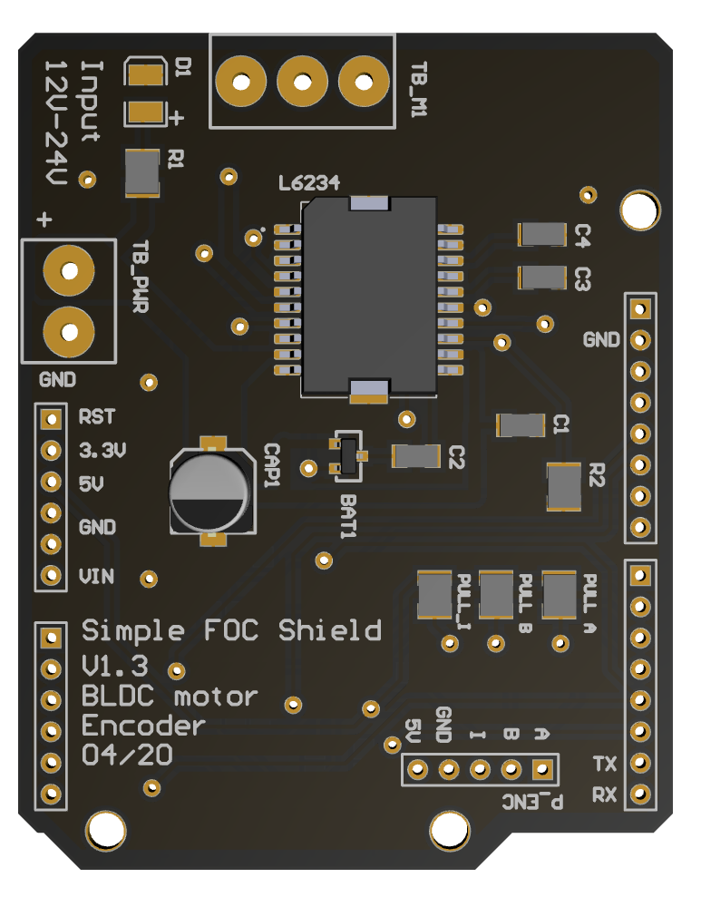 ](https://simplefoc.github.io/simplefoc_shield_product)| Arduino SimpleFOCShield | [More info](https://simplefoc.github.io/simplefoc_shield_product) | 25$
[
](https://simplefoc.github.io/simplefoc_shield_product)| Arduino SimpleFOCShield | [More info](https://simplefoc.github.io/simplefoc_shield_product) | 25$
[ ](https://www.ebay.com/itm/L6234-Breakout-Board/153204519965?hash=item23abb3741d:g:LE4AAOSwe35bctgg) | Dorotek L6234 breakout board| [Drotek](https://store-drotek.com/212-brushless-gimbal-controller-l6234.html), [Ebay](https://www.ebay.fr/itm/L6234-Breakout-Board-/153204519965) | 30$
[
](https://www.ebay.com/itm/L6234-Breakout-Board/153204519965?hash=item23abb3741d:g:LE4AAOSwe35bctgg) | Dorotek L6234 breakout board| [Drotek](https://store-drotek.com/212-brushless-gimbal-controller-l6234.html), [Ebay](https://www.ebay.fr/itm/L6234-Breakout-Board-/153204519965) | 30$
[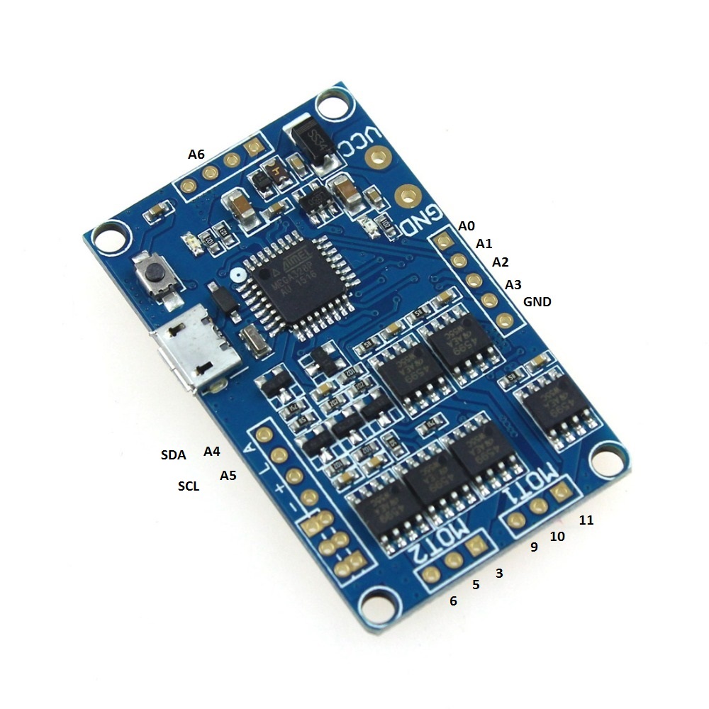 ](https://www.ebay.com/itm/HMBGC-V2-0-3-Axle-Gimbal-Controller-Control-Plate-Board-Module-with-Sensor/351497840990?hash=item51d6e7695e:g:BAsAAOSw0QFXBxrZ:rk:1:pf:1) | HMBGC V2.2 | [Ebay](https://www.ebay.com/itm/HMBGC-V2-0-3-Axle-Gimbal-Controller-Control-Plate-Board-Module-with-Sensor/351497840990?hash=item51d6e7695e:g:BAsAAOSw0QFXBxrZ:rk:1:pf:1) | 20$
## Table mount
There are surely many ways to mount this pendulum to the stable surface, in my case I hade on my hands a very robust vacuum suction cup holder which works perfectly for this application. It is not the cheapest solution though.
](https://www.ebay.com/itm/HMBGC-V2-0-3-Axle-Gimbal-Controller-Control-Plate-Board-Module-with-Sensor/351497840990?hash=item51d6e7695e:g:BAsAAOSw0QFXBxrZ:rk:1:pf:1) | HMBGC V2.2 | [Ebay](https://www.ebay.com/itm/HMBGC-V2-0-3-Axle-Gimbal-Controller-Control-Plate-Board-Module-with-Sensor/351497840990?hash=item51d6e7695e:g:BAsAAOSw0QFXBxrZ:rk:1:pf:1) | 20$
## Table mount
There are surely many ways to mount this pendulum to the stable surface, in my case I hade on my hands a very robust vacuum suction cup holder which works perfectly for this application. It is not the cheapest solution though.
 | Delkin Fat Gecko | [Ebay](https://www.ebay.com/itm/Delkin-Fat-Gecko-Stealth-Vacuum-Light-Mount-Holds-4-LB-Free-US-Shipping/141019370583?hash=item20d568d457:g:O6wAAMXQXMRR6EZ7) | 30$
---- | ---- | ---- | ----
The only important thing is that the pendulum base is fixed, everything else is the design choice :D
# Connecting all the components
In this project all the electronics components are:
[Arduino UNO](https://store.arduino.cc/arduino-uno-rev3) | [Arduino SimpleFOCShield](arduino_simplefoc_shield_showcase) | 2x [AMT 103 encoder](https://www.mouser.fr/ProductDetail/CUI-Devices/AMT103-V?qs=%2Fha2pyFaduiAsBlScvLoAWHUnKz39jAIpNPVt58AQ0PVb84dpbt53g%3D%3D) | [iPower GM4108-120T](https://shop.iflight-rc.com/index.php?route=product/product&product_id=217&search=GM4108H-120T)
--- | --- | --- | ---
| Delkin Fat Gecko | [Ebay](https://www.ebay.com/itm/Delkin-Fat-Gecko-Stealth-Vacuum-Light-Mount-Holds-4-LB-Free-US-Shipping/141019370583?hash=item20d568d457:g:O6wAAMXQXMRR6EZ7) | 30$
---- | ---- | ---- | ----
The only important thing is that the pendulum base is fixed, everything else is the design choice :D
# Connecting all the components
In this project all the electronics components are:
[Arduino UNO](https://store.arduino.cc/arduino-uno-rev3) | [Arduino SimpleFOCShield](arduino_simplefoc_shield_showcase) | 2x [AMT 103 encoder](https://www.mouser.fr/ProductDetail/CUI-Devices/AMT103-V?qs=%2Fha2pyFaduiAsBlScvLoAWHUnKz39jAIpNPVt58AQ0PVb84dpbt53g%3D%3D) | [iPower GM4108-120T](https://shop.iflight-rc.com/index.php?route=product/product&product_id=217&search=GM4108H-120T)
--- | --- | --- | ---
 |
|  | |
| |  ## Encoder 1 (motor)
- Channels `A` and `B` are connected to the encoder connector `P_ENC`, terminals `A` and `B`.
## Encoder 2 (pendulum)
## Encoder 1 (motor)
- Channels `A` and `B` are connected to the encoder connector `P_ENC`, terminals `A` and `B`.
## Encoder 2 (pendulum)
Pinout restriction- Encoder channels `A` and `B` are connected to the pins `A0` and `A1`. ## Motor - Motor phases `a`, `b` and `c` are connected directly the motor terminal connector `TB_M1`
Arduino UNO doesn't have enough hardware interrupt pins for two encoders therefore we need to use the software interrupt library.
Alignment# Arduino code Let's go through the full code for this project and write it together. First thing you need to do is include the `SimpleFOC` library: ```cpp #include
Motor phasesa,b,cand encoder channelsAandBhave to have the same orientation for the algorithm to work. But don't worry about it too much. Connect it initially as you wish and then if the motor locks in place reverse phaseaandbof the motor, that should be enough.
For more configuration parameters of the encoders please check the *SimpeFOClibrary*'s Encoder class docs.
## Encoder 2 (pendulum) code
We define the pendulum as the `Encoder` class with the A and B channel pins and number of impulses per revolution.
```cpp
// define Encoder
Encoder pendulum = Encoder(A0, A1, 1000);
```
Then we define the buffering callback functions.
```cpp
// channel A and B callbacks
void doPA(){pendulum.handleA();}
void doPB(){pendulum.handleB();}
```
Next we define the `PciManager` pin change listeners:
```cpp
// pin change listeners
PciListenerImp listenerPA(pendulum.pinA, doPA);
PciListenerImp listenerPB(pendulum.pinB, doPB);
```
In the `setup()` function first we initialize the pendulum encoder:
```cpp
// initialize encoder hardware
pendulum.init();
```
And then instead of calling `pendulum.enableInterrupt()` function we use the `PciManager` library interface to attach the interrupts.
```cpp
// interrupt initialization
PciManager.registerListener(&listenerPA);
PciManager.registerListener(&listenerPB);
```
And that is it the pendulum is ready, let's setup the motor.
## Motor code
First we need to define the `BLDCMotor` class with the number of pole pairs(`11`) of the motor.
```cpp
// define BLDC motor
BLDCMotor motor = BLDCMotor(11);
```
If you are not sure what your pole pairs number is please check the find_pole_pairs.ino example.
Next we need to define the `BLDCDriver3PWM` class with the PWM pin numbers and the driver enable pin.
```cpp
// define BLDC driver
BLDCDriver3PWM driver = BLDCDriver3PWM(9, 10, 11, 8);
```
Then in the `setup()` we configure first the voltage of the power supply if it is not `12` Volts and initialize and link the driver.
```cpp
// power supply voltage
// default 12V
driver.voltage_power_supply = 12;
driver.init();
motor.linkDriver(&driver);
```
Then we tell the motor which control loop to run by specifying the `motor.controller` variable.
```cpp
// set control loop type to be used
// ControlType::voltage
// ControlType::velocity
// ControlType::angle
motor.controller = ControlType::voltage;
```
For more information about the voltage control loop please check the doc.Next we connect the encoder to the motor, do the hardware init and init of the Field Oriented Control. ```cpp // link the motor to the sensor motor.linkSensor(&encoder); // initialize motor motor.init(); // align encoder and start FOC motor.initFOC(); ``` The last peace of code important for the motor is of course the FOC routine in the `loop` function. ```cpp void loop() { // iterative FOC function motor.loopFOC(); // iterative function setting and calculating the angle/position loop // this function can be run at much lower frequency than loopFOC function motor.move(target_voltage); } ``` Now we are able to read the two encoders and set the voltage to the motor, now we need to write the stabilization algorithm.
For more configuration parameters and control loops please check the *SimpleFOClibrary*'s BLDCMotor class doc.
## Control algorithm code
The control algorithm is divided in two stages. Stabilization and swing-up.
#### Stabilization
In order to stabilize the pendulum we will be using a state space controller which means that it takes in consideration all three variables important for this pendulum system:
- pendulum angle - `p_angle`
- pendulum velocity - `p_vel`
- motor velocity - `m_vel`
The controller code is very simple at the end, it just calculates the linear control rule:
```cpp
target_voltage = 40*p_angle + 7*p_vel + 0.3*m_vel;
```
The gains `40`,`7` and `0.3` you can imagine as weights, which tell how much we care about these variables. The highest weight is obviously on the pendulum angle and the smallest is on motor velocity that makes sense. Basically if we set `0` to the motor velocity weight, your pendulum will still be stable but your motor will probably never stop spinning. It will always have some velocity. On the other hand if you put it much higher, you will probably prioritize your motor movements over the stability and your pendulum will no longer be stable. So there is a tradeoff here.
This is a very simple explanation of a relatively complex topic and I would like to point you toward a nice [youtube video](https://www.youtube.com/watch?v=E_RDCFOlJx4) explanation of similar approaches.
Also maybe interesting to say is that for a system like this one there is really no need to run it with the sample times less then 20ms. In my case I have run it at ~25ms, but you can go even to 50ms.
NOTE#### Swing-up The swingup implemented in this example is the simples one possible, that is always good, it means that the hardware is well designed so you dont need to make some fancy algorithm to make it work :D This is hte code of the swing-up: ```cpp target_voltage = -_sign(pendulum.getVelocity())*motor.voltage_power_supply*0.4; ``` What it does really is it checks which direction the pendulum is moving `sign(pendulum.getVelocity())` and sets the very high voltage value `motor.voltage_power_supply*0.4` in the opposite direction (`-`). It means that the algorithm is going to try to accelerate the movement of the pendulum (because the pendulum acceleration is caused as the reaction of the motor acceleration, but inverse direction). The voltage value you are setting is something you will tune. I have found that for my pendulum 40% of the maximum voltage was enough to make the pendulum swing up. More voltage would make it swing up too fast and the pendulum would not be able to stabilize when it reaches the top. Much less voltage would not be enough for the pendulum to swing up at all. #### The integration Now we jsut need to decide when do we do the swing up and when do we do the stabilization. Basically we need to decide the angle from which we decide that it is not possible to recover and we should proceed with the swing-up. I my case I have decided it is `0.5 radians`, `~30degrees`. So the full control algorithm code looks like this: ```cpp // control loop each ~25ms if(loop_count++ > 25){ // calculate the pendulum angle float pendulum_angle = constrainAngle(pendulum.getAngle() + M_PI); float target_voltage; if( abs(pendulum_angle) < 0.5 ) // if angle small enough stabilize target_voltage = 40*pendulum_angle + 7*pendulum.getVelocity() + 0.3*motor.shaftVelocity(); else // else do swing-up // sets 40% of the maximal voltage to the motor in order to swing up target_voltage = -_sign(pendulum.getVelocity())*motor.voltage_power_supply*0.4; // set the target voltage to the motor motor.move(target_voltage); // restart the counter loop_count=0; } ``` And that is it guys we can read our pendulum angle, we can control the motor, and we have our control algorithm. Lets write the full code! ## Full Arduino code For the full code I have just added a function `constrainAngle()` to constrain the pendulum angle in between -180 and 180 degrees and moved the stabilization part of the controller to the stand-alone function `controllerLQR()`. ```cpp #include
The FOC algorithmmotor.loopFOC()will run ~1ms but the control algorithm and the functionmotor.move()will be downsampled to ~25ms.