# 电路相关
**Repository Path**: xzmx/circuit-related
## Basic Information
- **Project Name**: 电路相关
- **Description**: No description available
- **Primary Language**: Unknown
- **License**: Not specified
- **Default Branch**: master
- **Homepage**: None
- **GVP Project**: No
## Statistics
- **Stars**: 0
- **Forks**: 0
- **Created**: 2025-05-10
- **Last Updated**: 2025-05-18
## Categories & Tags
**Categories**: Uncategorized
**Tags**: None
## README
关键步骤:


最终效果说明:
http://svwxgj6ga.hd-bkt.clouddn.com/md-self/%E5%B0%8F%E5%A4%9C%E7%81%AF-%E6%9C%80%E7%BB%88%E6%95%88%E6%9E%9C.mp4?e=1746881736&token=QNw9SOe0lQDlGLAW9ES2bOoBJvK1disdnBI96c9j:0-5uXznAGQgZxNJ_xE6Hx6SN6zE=
补充说明:
http://svwxgj6ga.hd-bkt.clouddn.com/md-self/%E5%B0%8F%E5%A4%9C%E7%81%AF-%E8%A1%A5%E5%85%85%E8%AF%B4%E6%98%8E.mp4?e=1746881114&token=QNw9SOe0lQDlGLAW9ES2bOoBJvK1disdnBI96c9j:-9d-OlEGbP19JqjWmnWou5ShbrA=
下面说下接线技巧:
【接线技巧1】:
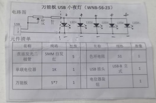
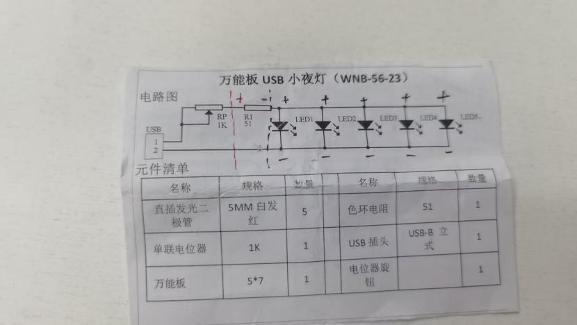
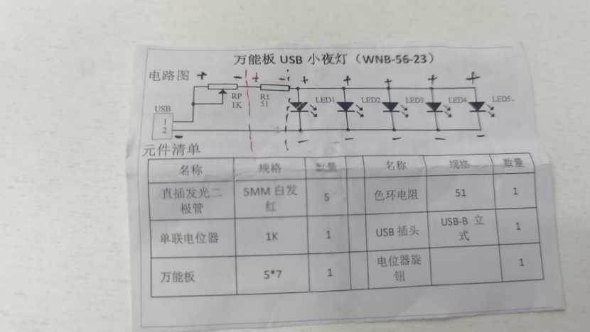
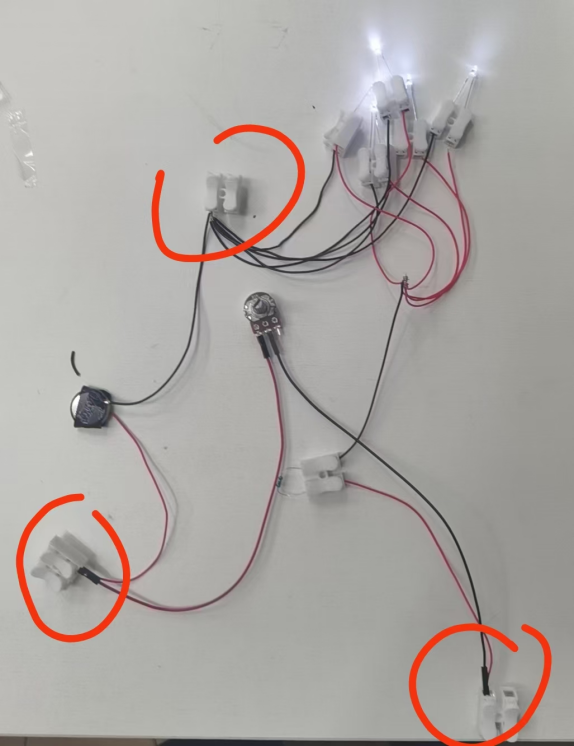
【电路图:】
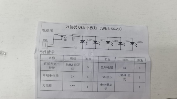
现在发这张图是电路图。然后电路图上可以看到:5个二极管是并联的。
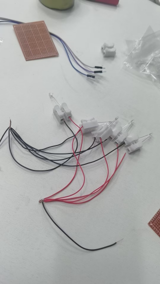
并联的5个二极管,接法上有一个技巧:就是每一个管呢,事先接好线之后,就是一个个单元都需要用电池测一下它会不会亮。以免电路装起来后,不知道哪里是断开的。
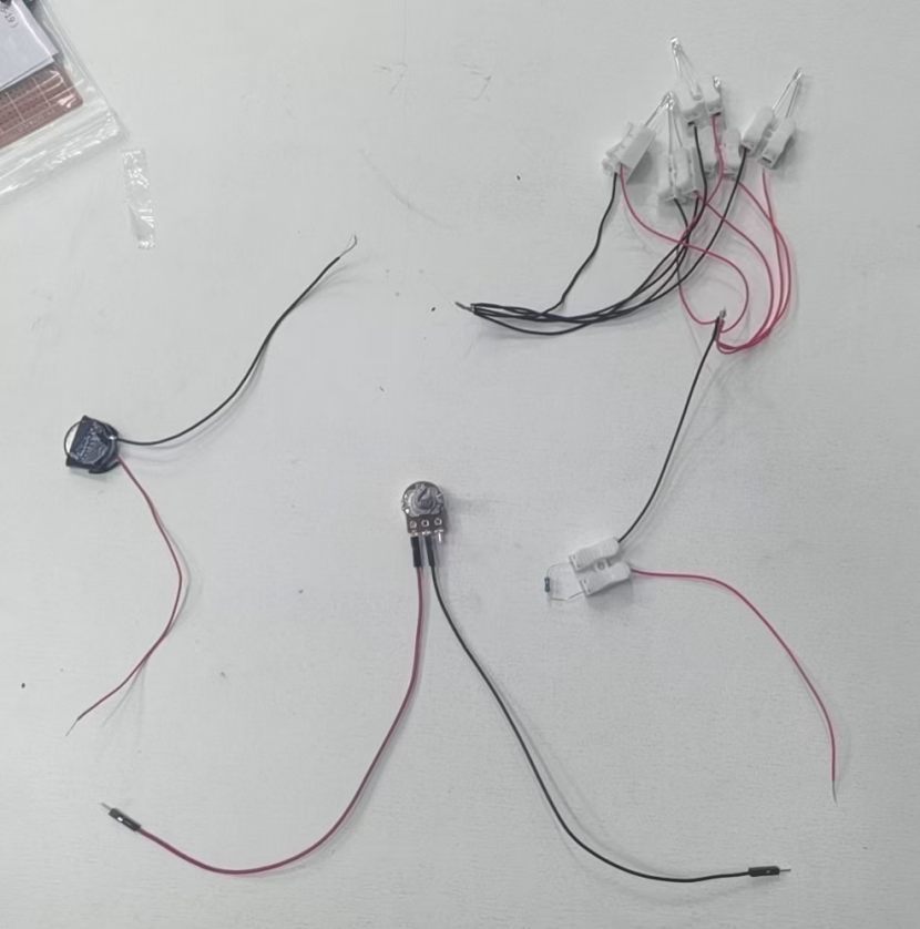
因为二极管是有正负极的啊,所以我们要用红色的线接正极,然后蓝黑色的线接负极。以作区分。
演示如下:
教学时,每一个都要先验证通路。
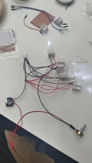
这个电路的整体电压是5伏左右。所以实际电路中,我们用两个纽扣电池来作为电源。或者用usb插头来作为电源。

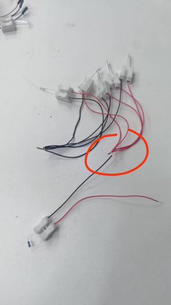
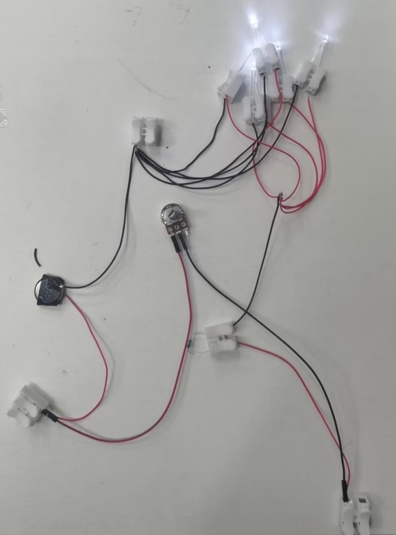
因为五个二极管接法都是并联的。最终效果是这样:
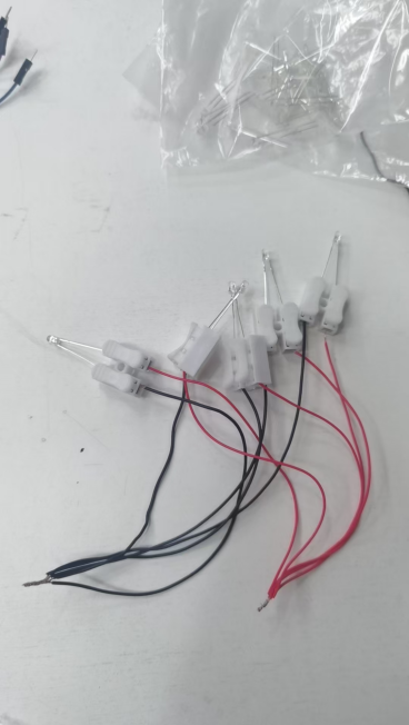
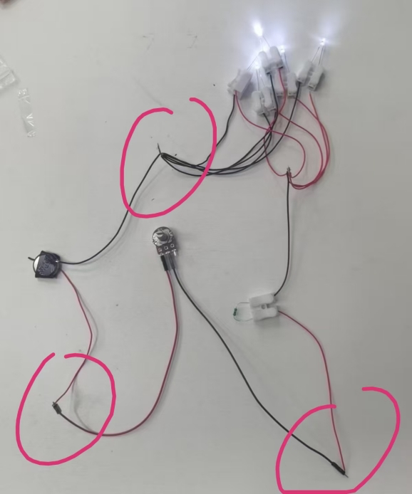
所有红色的线拧在一起。
所有黑色的线也拧在一起。
如图所示,正极在同一侧,负极在同一侧。
【接线技巧2】:
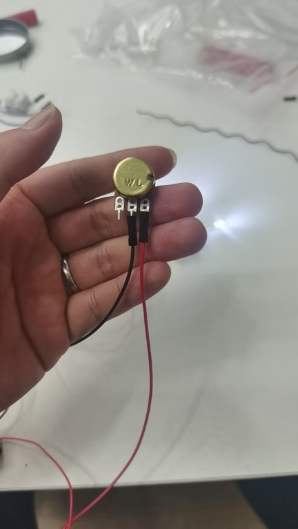
接下来接电阻,电阻是没有正负极的。但是为了方便演示和教学,我们依旧还是一根红,一根黑。(红色代表电源正极从这里进,从黑色流出。)
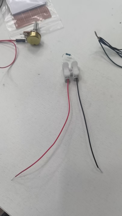
图中我用红笔标出。可以看到黑色,之后应该接红色的并联二极管(5个)。所以接法如下:
进一步可以看到负极直接接到usb的负极(或电源负极),正极接电位起,然后再接入usb正极(或电源正极。)

【接线技巧3】:
刚才提到的关键技巧:电位器接法。
直接正极接入电源
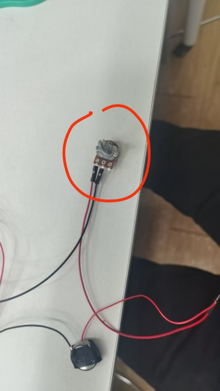
其中电位器是用杜邦公母线,接入。
杜邦线的头是有齿的,其中一个面,插的较为紧。
如果不用杜邦线,只要能固定住,就可以。(电位器上有小孔,绑上去也行)
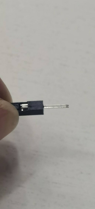
公母都有齿。
【接线技巧4】:
最后完成电路:
可以看到电阻器的正极端接入电位器的负极。
电位器的正极接入电源负极正极。
电源负极接入二极管负极。
把它们接上即可完成电路。
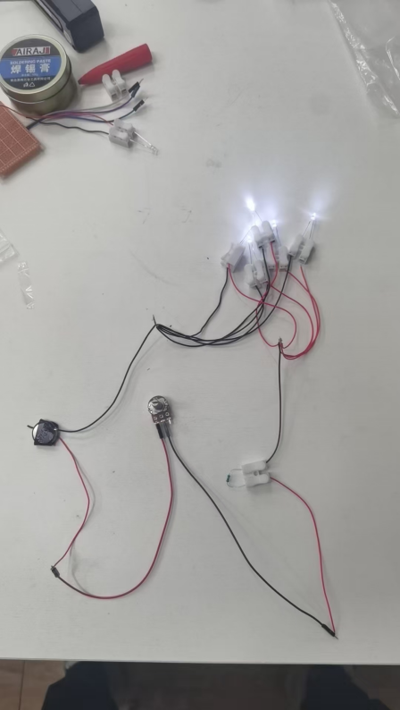
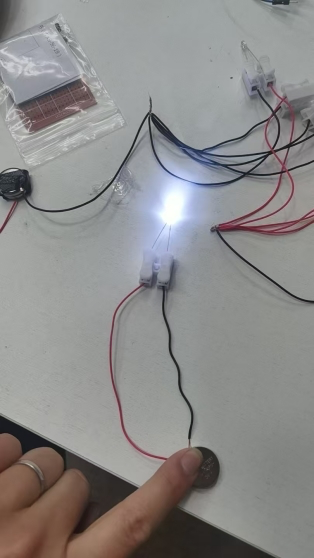
可以看到此时灯亮了;
如果旋转电位器,等可以调节亮度;
如果希望接线牢靠,也可以用接线端子,来接。
【最终效果图】:
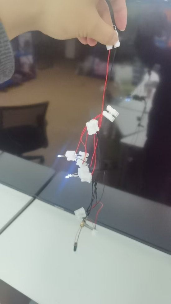
这样接线还是比较牢固的,拿起来也不会断开电路。
最后补一句:电池要两粒(6v),忘记刚才视频有没说了。USB是5v。大于5v就可以。
教程完毕。