

代码拉取完成,页面将自动刷新

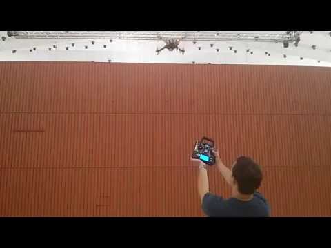
This is a flight controller used for a quadcopter in X-configuration.
It is written for the Tiva C Series TM4C123G LaunchPad running at 80 MHz.
More information can be found at the following blog posts: http://blog.tkjelectronics.dk/2015/01/launchpad-flight-controller and http://blog.tkjelectronics.dk/2015/08/bachelors-thesis-launchpad-flight-controller.
Some video demonstrations of the flight controller can be seen at my YouTube channel.
The report I wrote for my Bachelor's thesis can be found in the docs folder. The 3D model and Matlab code can be found in there as well.
| Pin | Connection |
|---|---|
| PB6 | Motor 1 |
| PB7 | Motor 2 |
| PB4 | Motor 3 |
| PB5 | Motor 4 |
| PC6 | CPPM input |
| PA6 | SCL |
| PA7 | SDA |
| PE2 | MPU-6500/MPU-9250 INT |
| PC5 | Sonar echo |
| PE0 | Sonar trigger |
| PB0* | UART1 RX |
| PB1* | UART1 TX |
| PD2 | Buzzer |
| PE3 | HMC5883L DRDY |
* UART1 is connected to an HC-06 Bluetooth module running at a baudrate of 115200. Not 5V tolerant!, so make sure your Bluetooth module outputs 3.3 voltage level or use a logic level converter.
The MPU-6500/MPU-9250, HMC5883L, BMP180 and LIDAR-Lite v3 are connected via I2C if they are used.
The motor layout follows the Naze32 in x-configuration i.e. motor 1 is bottom right, motor 2 is top right, motor 3 is bottom left and motor 4 is top left when looking from the back. Motor 1 and 4 should be spinning clockwise and motor 2 and 3 should be spinning counterclockwise.
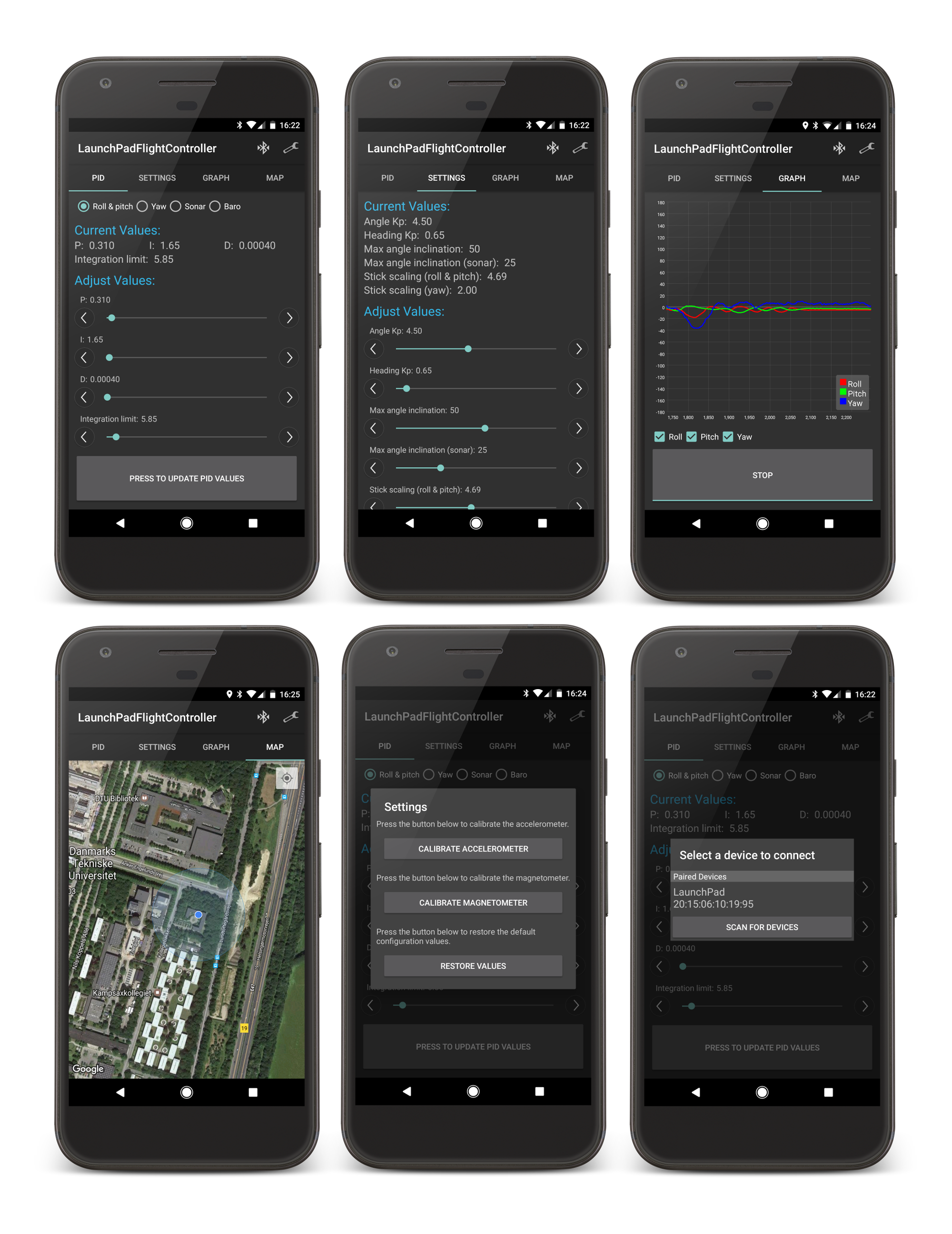
Make sure that roll increases when tilting quadcopter to the right, pitch increases when pitching quadcopter upward and yaw increases when rotation quadcopter clockwise. This can be displayed using the graph menu in the Android application.
The flight controller is armed by having the throttle low and the rudder to the right. The flight controller is disarmed again by having the throttle low and the rudder to the left.
#define ONESHOT125 1 in PPM.c and set line to 0 if your ESCs does not support OneShot125, if you are in doubt, then set the value to 0.mpu6500BoardOrientation and hmc5883lBoardOrientation in MPU6500.c and HMC5883L.c respectively.
WARNING: Take propellers OFF when testing and calibrating ESCs!!
In order calibrate the ESCs you need to do the following procedure:
The calibration is canceled if the buttons are not held down during the whole procedure or the reset is not performed by a power on reset. The former allows the user to cancel the calibration at any time by releasing the switches and the latter prevents the user from accidentally resetting the board without also resetting the ESCs, for instance by pressing the reset button on the board.
The last step is to calibrate the accelerometer and magnetometer. The accelerometer is calibrated by putting the quadcopter horizontal and activating the calibration routine via the Android application's settings menu. It is important that the quadcopter is kept still while running the accelerometer calibration routine. When the calibration is done a long beep will be played using the onboard buzzer.
The magnetometer calibration routine is activated similar to the accelerometer by using the Android application. The blue LED will turn on, indicating that the calibration procedure is activated. Now rotate the quadcopter along all three axis slowly in order to find the minimum and maximum values. The user has 30 seconds to rotate the quadcopter. Once the calibration is done the blue LED will be turned off and a long beep will be played.
It is a good idea to confirm that the estimated angles are all correct by using the graph menu in the Android application.
There is no need to calibrate the gyroscope, as this is done at every startup.
![]()
The Android source code is available at the following repository: https://github.com/Lauszus/LaunchPadFlightControllerAndroid.
A simple GUI can be found inside the GUI directory. It can be used to visualise the orientation of the flight controller.
In order to built this project you need to download Keil µVision IDE 5 or use Make.
If you are using Keil µVision IDE 5, then simply open the project file.
If you are using Make, then you will need to first download and install gcc-arm-none-eabi and then install lm4tools.
lm4tools can be installed like so:
$ git clone https://github.com/utzig/lm4tools.git
$ cd lm4tools/
$ cd lm4flash/ && make
$ sudo cp lm4flash /usr/bin/
If you are on a Mac, I recommend installing gcc-arm-none-eabi using Homebrew like so:
$ brew tap PX4/homebrew-px4
$ brew update
$ brew install gcc-arm-none-eabi
OpenOCD can be installed via Homebrew as well:
$ brew install openocd
Now run the following commands:
$ openocd --file /usr/local/share/openocd/scripts/board/ek-tm4c123gxl.cfg

$ arm-none-eabi-gdb gcc/LaunchPadFlightController.axf
(gdb) target extended-remote :3333
(gdb) monitor reset halt
(gdb) load
(gdb) monitor reset init
More information regarding hardware debugging can be found at the Wiki.
A lot of the inspiration for this code came from Cleanflight and other open source flight controller projects.
For more information send me an email at lauszus@gmail.com.
此处可能存在不合适展示的内容,页面不予展示。您可通过相关编辑功能自查并修改。
如您确认内容无涉及 不当用语 / 纯广告导流 / 暴力 / 低俗色情 / 侵权 / 盗版 / 虚假 / 无价值内容或违法国家有关法律法规的内容,可点击提交进行申诉,我们将尽快为您处理。


